
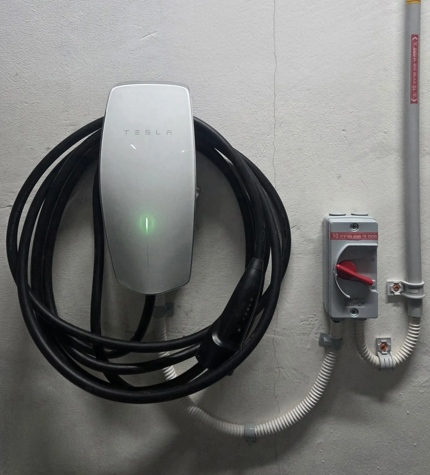
An EV charger is more than an electrical outlet
Electric vehicle supply equipment, commonly called EVSE, is a control and protection system that manages energy transfer between the electrical supply and the vehicle. It verifies the cable connection, the vehicle's readiness to charge, and the absence of an electrical fault before power is enabled.
With AC charging, the station supplies controlled alternating current and the vehicle's onboard charger converts it to the direct current required by the battery. With DC charging, conversion takes place inside the external charger and controlled direct current is supplied to the vehicle battery system.
AC and DC are different charging technologies
AC charging
AC is well suited to homes, parking facilities, and locations where a vehicle remains parked for several hours. The station is smaller and simpler because AC-to-DC conversion takes place inside the vehicle.
- Single-phase or three-phase, depending on the supply.
- Power is also limited by the vehicle's onboard charger.
- Ideal for daily overnight or workplace charging.
DC charging
The charger contains high-power conversion modules that create direct current at the voltage requested by the battery. It communicates continuously with the vehicle's battery management system and adjusts voltage and current during the session.
- Designed for rapid, high-power charging.
- Requires stronger electrical infrastructure and cooling.
- Common at public sites, highway locations, and fleets.
What happens when the cable is connected
The station and vehicle complete a controlled sequence before charging. The system detects the connection, verifies connector locking and cable capability, communicates the available current, and waits for the vehicle to confirm readiness. Main power contacts close only after these checks.
- Detect the cable and vehicle.
- Verify grounding, system condition, and protection.
- Communicate the available current.
- Receive vehicle permission to begin charging.
- Continuously monitor current, voltage, and temperature.
- Stop power in a controlled manner before opening the contacts.
Advanced digital communication can support automatic identification, payment, Plug & Charge, smart charging, and bidirectional power functions when the vehicle, charger, and energy system all support them.
Main components inside a charging station
Runs the charging sequence, reads sensors, and communicates with the vehicle.
Connects and disconnects the main circuit after safety checks.
Current, voltage, and energy sensors support control and consumption records.
Detect leakage current, overheating, abnormal voltage, and other faults.
Wi-Fi, Ethernet, cellular, or Bluetooth for local and remote management.
Designed for current, temperature, weather exposure, and repeated use.
DC chargers also include power-conversion modules, filters, isolation components, fans or liquid cooling, and a more complex control system.
Smart charging and load management
Smart charging allows a station to adjust power according to the total load at the property. A meter or current sensor measures building consumption, and the system raises or lowers charging current so the main connection remains within a defined limit.
Home load management: real-time power sharing between the building and vehicle.
Multiple chargers: allocation of available capacity among several vehicles.
Solar integration: prioritizing charging when local generation is available.
Scheduling: starting at a selected time or electricity tariff period.
Remote management: status, history, access control, and software updates.
At public and commercial sites, OCPP is used for communication between charging stations and central management systems. Depending on the implementation, it can support monitoring, authorization, fault handling, pricing, and software updates.
Protection and safety technologies
An EV charger can operate at significant load for many hours, so safety begins with the electrical infrastructure. Cable size, circuit breaker, RCD, grounding, isolation, and panel equipment must suit the charger specifications and site conditions.
- Grounding verification before power is enabled.
- AC and DC leakage detection according to charger design and external protection.
- Protection against overcurrent, short circuit, and abnormal voltage.
- Temperature monitoring in the connector, cable, or power electronics.
- Connector locking and prevention of disconnection under load.
- An enclosure suited to sunlight, rain, dust, and mechanical exposure.
Where charging technology is going
The next generation of charging systems connects the vehicle, building, and electrical grid. Advanced communication supports Plug & Charge, in which the vehicle can be identified automatically after connection, together with more precise power control.
Bidirectional charging can allow a supported vehicle battery to supply energy to a building or the grid. V2H and V2G require compatibility across the vehicle, charger, power converter, energy-management system, and local rules.
Other developments include energy-storage integration, liquid-cooled high-power DC cables, automatic connection systems, and energy management based on forecasts of consumption and solar production.
Choosing the right technology
Before purchasing a charger, check the vehicle connector, the onboard charger's actual power capability, property supply, cable distance, parking environment, and the need for dynamic load management or app connectivity.
The best solution is not necessarily the highest-power charger. It is the system that correctly matches the vehicle, infrastructure, and daily use.
Standards and technologies referenced
This guide is based on widely used conductive-charging principles, including the IEC 61851 family, ISO 15118 communication, and OCPP. Exact implementation depends on the vehicle, charger model, manufacturer instructions, and local requirements.
Need a charger matched to the vehicle and property?
Send photos of the electrical panel, parking space, and expected cable route for an initial assessment.